All-on-X Overview
The idea of providing an All-on-X implant supported prosthesis to a patient can seem overwhelming and complicated. Which of course, it is. All-on-X treatment is at least a full arch rehabilitation, and almost always includes extra considerations relating to surgical technique and treatment sequencing. In this way, the dentist interested in restoring an edentulous arch with a full arch, implant supported dental prosthesis is encouraged to attain not only specific training in All-on-X techniques, but have advanced knowledge of gnathology, occlusion, and the functionally cosmetic demands of conventional denture design. The idea of referring a patient to an oral surgeon for four implants and taking a in impression of the implant position to send to a laboratory to fabricate a full arch prosthesis is insufficient in plan and execution, and will most likely yield poor results for the patient and expensive mistakes for the doctor.
A strong and compelling argument can be made that the first step of providing successful All-on-X treatment is denture fabrication, especially in the case of a totally edentulous patient. Prosthodontic principles such as vertical dimension of occlusion, incisal edge position, tooth size and shape, and phonetic considerations must all be determined prior to definitive restorative therapy. Perhaps the best way to ensure a functional and cosmetic implant supported denture that allows the stomatognathic system to function optimally is to first create a conventional denture that looks good, feels good, and chews good (well), without creating occlusal-muscle problems or speech difficulties. A full arch conventional denture can be used as an interim restoration that fulfills functional and social needs during the healing phase after implant surgery.
Figure 1a; The edentulous mandible.
Figure 1b; A conventional mandibular denture
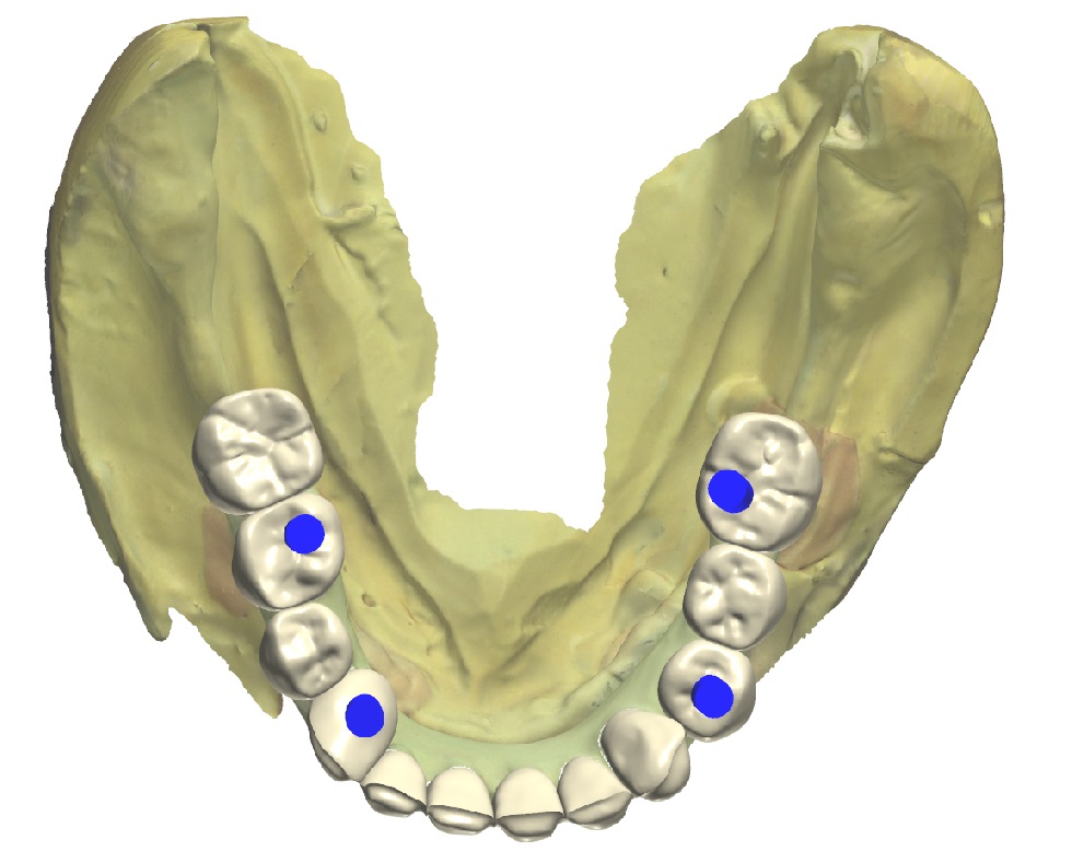
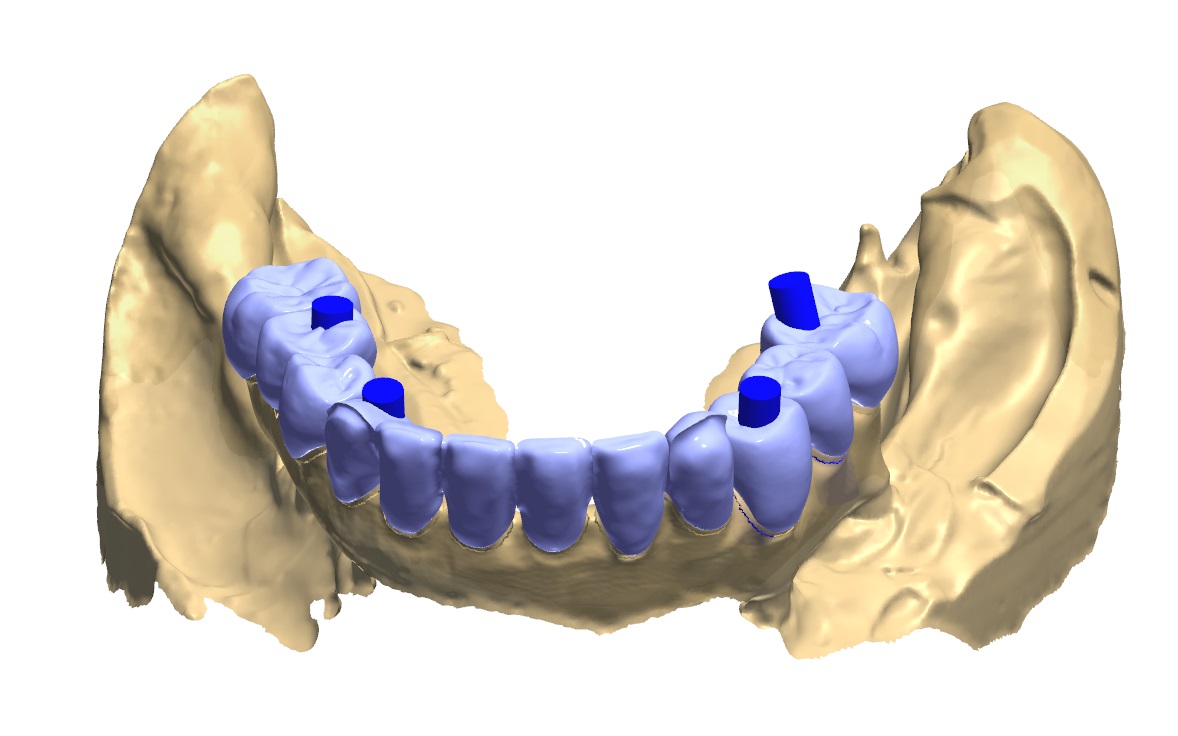
Once the provider has established an appropriate VDO and functionally cosmetic tooth position, implant placement relative to vital structures and bone volume and quality can be considered (figure 2). Ideally, implant placement should pay some credence to the final design of the restoration. Currently, integrating digitized models or intra-oral scans with Cone Beam Computed Tomography can provide accurate treatment planning and surgical guidance for such a procedure. If the patient has abundant quantities of dense bone is present, the surgical placement of dental implants may be done free hand, and may even utilize angulation guides from dental implant manufacturers to assist in implant placement. Of course, a surgical drilling guide can be utilized as well, and in either case, there are distinct advantages to evaluating a patient three dimensionally with integrated Standard Tesselation Language (STL) renderings of teeth stitched to a CBCT versus historical methods of 2D panoramic films and stone models. If the surgery is to be carried out with the use of a guide, rigid fixation of the drilling appliance is essential. If the patient is fully or partially dentate at the time of surgery, teeth without severe periodontal disease or mobility can provide hard tissue support for the guide (figure 3a, 3b). If the patient is edentulous, fixation screws can aide in holding the guide in a fixed position and ensure accurate execution of the surgical plan. After implant placement, an experienced provider may immediately temporize the patient with an interim fixed denture in the form of a new prosthesis or a converted existing denture, given good primary stability of each implant. In other cases, healing abutments may be placed and the existing interim denture adjusted to accommodate them. The implants may also simply receive cover screws and be covered with soft tissue to allow healing or stage financing further treatment while wearing a functional interim conventional denture.
Figure 2; Digitally assisted planning of the implant position.
Figure 3a; Surgical guide consistent with serial extractions and maintenance of selected teeth for rigid support to accommodate proposed implant position.
Figure 3b; Pre-operative and post-operative panoramic radiographs.
After healing, the implants can be restored with a full arch prosthesis. There are many ways to achieve this. Locators or friction fit abutments may be utilized to retain a denture that is essentially “fixed” but can be removed by the patient for hygiene purposes. A bar may be utilized, or the prosthesis may be screwed directly to abutments already torqued to the fixtures. Inter-occlusal space is an important consideration here, as different prosthetic designs require different amounts of space to accommodate necessary components; 15 mm from the implant platform to the opposing occlusal surface is a good benchmark number to consider here. Ostensibly, even the task of being able to appropriately identify and name the components required for completing such an intricate dental prosthesis is itself challenging. Commonly, something called a Multi-Unit Abutment (MUA), or Multi-Base Abutment (MBA) is utilized as an abutment to link the fixture to the prosthesis. The MUAs are commonly inserted to a definitive torque of 25 - 35 Ncm (Figure 4). MUAs can be be offset to accommodate implants that were placed at an angle to avoid the mental foramen or maxillary sinus. Once the MUAs are in place, they stay put (barring implant complications). The MUAs have their own internal housing that will receive a screw to retain the prosthesis, which is torqued at a slightly lower value than the MUAs, commonly 15 Ncm.
Figure 4; Four multi-base abutments inserted to the fixture to a torque value of 25 Ncm.
Once the MUAs are placed, an abutment level impression is made to pick-up the implants’ spatial location and orientation relative to the arch. An impression post is screwed into each MUA, and the impression is taken with an open tray (figure 5). Many methods to ensure an accurate transfer of this information exist. In the pictured case, a 3D printed custom tray with rigid chimneys was used to provide stability of the impression posts in the impression, thereby ensuring accurate transfer of the implants’ location. Commonly, the impression posts may be joined with rigid fixation by way of pattern-resin covered floss or rigid wire that is luted to each of the impression posts. In any case, the next step is to have a master cast made with implant analogs in the stone cast. At this point, a verification jig is made on the master cast using replica cylinders. Clinically, the verification jig is inserted into the patient’s mouth and evaluated for accuracy and passive fit. It is essential that passive fit is attained, as a prosthesis that does not fit passively can contribute to bio-mechanical complications. To verify passive fit, the jig should seat evenly across all MUAs. Furthermore, the single screw technique should be utilized, whereby a screw is tightened into each MUA without any portion of the verification jig lifting out of place. Additionally, radiographs can be made to evaluate the intimacy of fit between the components. If the jig does not fit evenly or passively, do not panic. The jig can be sectional and re-luted with pattern resin to produce a now accurate jig (note the complete set time of the pattern resin here, as shrinkage of the resin can occur if the jig is removed prematurely)(figure 6). If the verification jig is altered intra-orally, the master cast is altered by the lab accordingly, as the implant analog location will have been found to be different from the initial impression and cast (figure 7). In this case, a wax rim was made to fit over the verification jig. This wax rim was based on the initial articulation of study casts using a duplicate denture as a guide for the final VDO. The wax rim can be altered to the desired VDO chair-side before an inter-occlusal record is made (figure 8).
Figure 5; Custom tray, and Multi-Base Abutment impression posts in place.
Figure 6; Laboratory fabricated verification jig and luting of the sectioned jig intra-orally to ensure passive fit of the framework.
Figure 7; Definitive altered cast with verification jig and wax bite rim at the patient’s current Vertical Dimension of Occlusion (VDO).
Figure 8; A duplicated denture was utilized in approximating the desired VDO of the definitive casts. The wax bite rim was built to the current VDO and an inter-occlusal record was made intra-orally after the wax bite rim position was adjusted and verified.
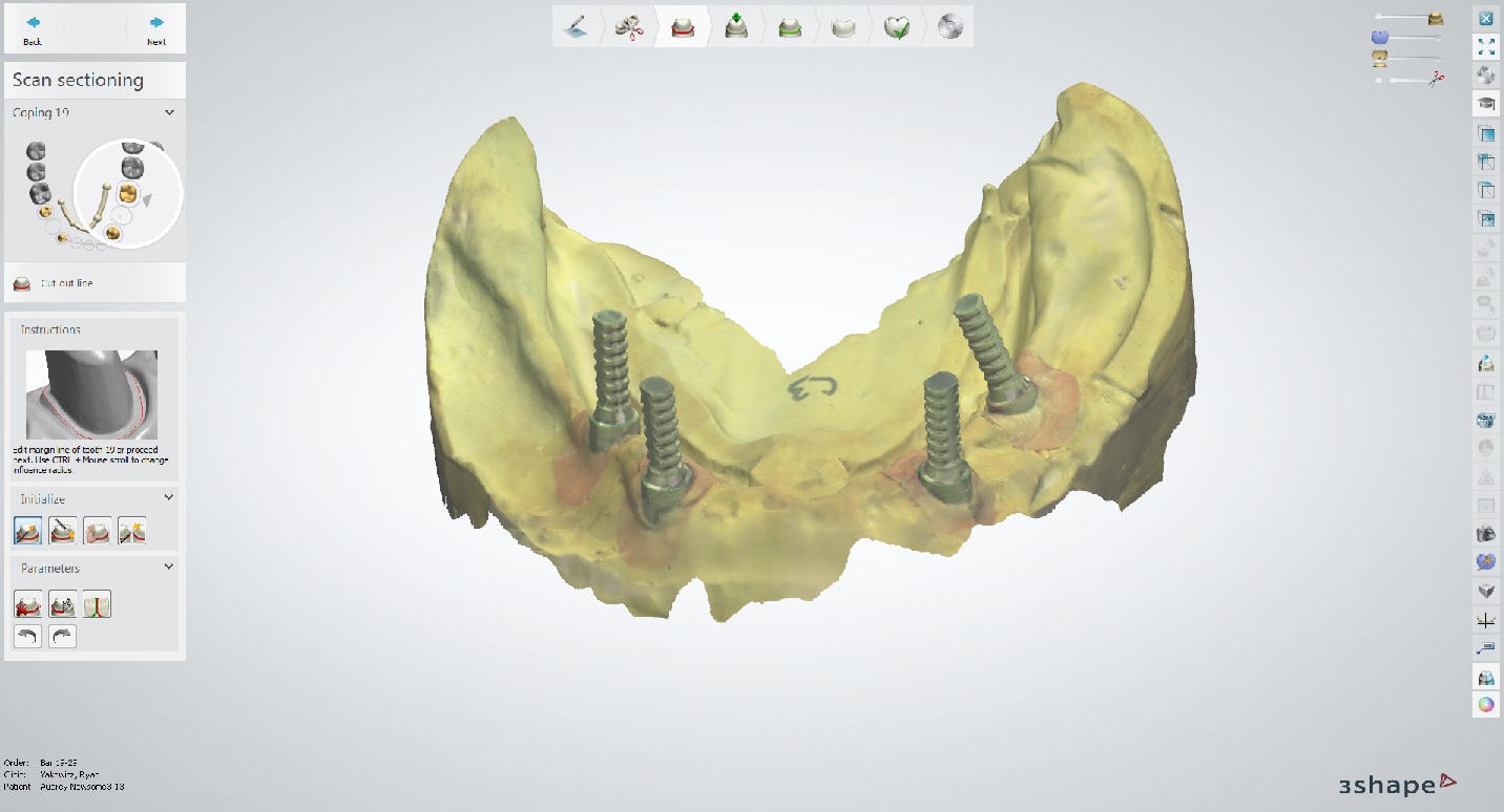
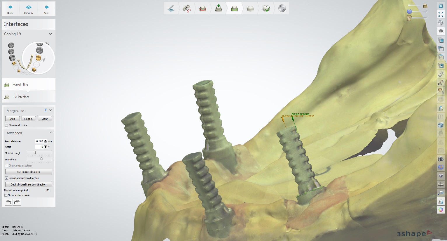
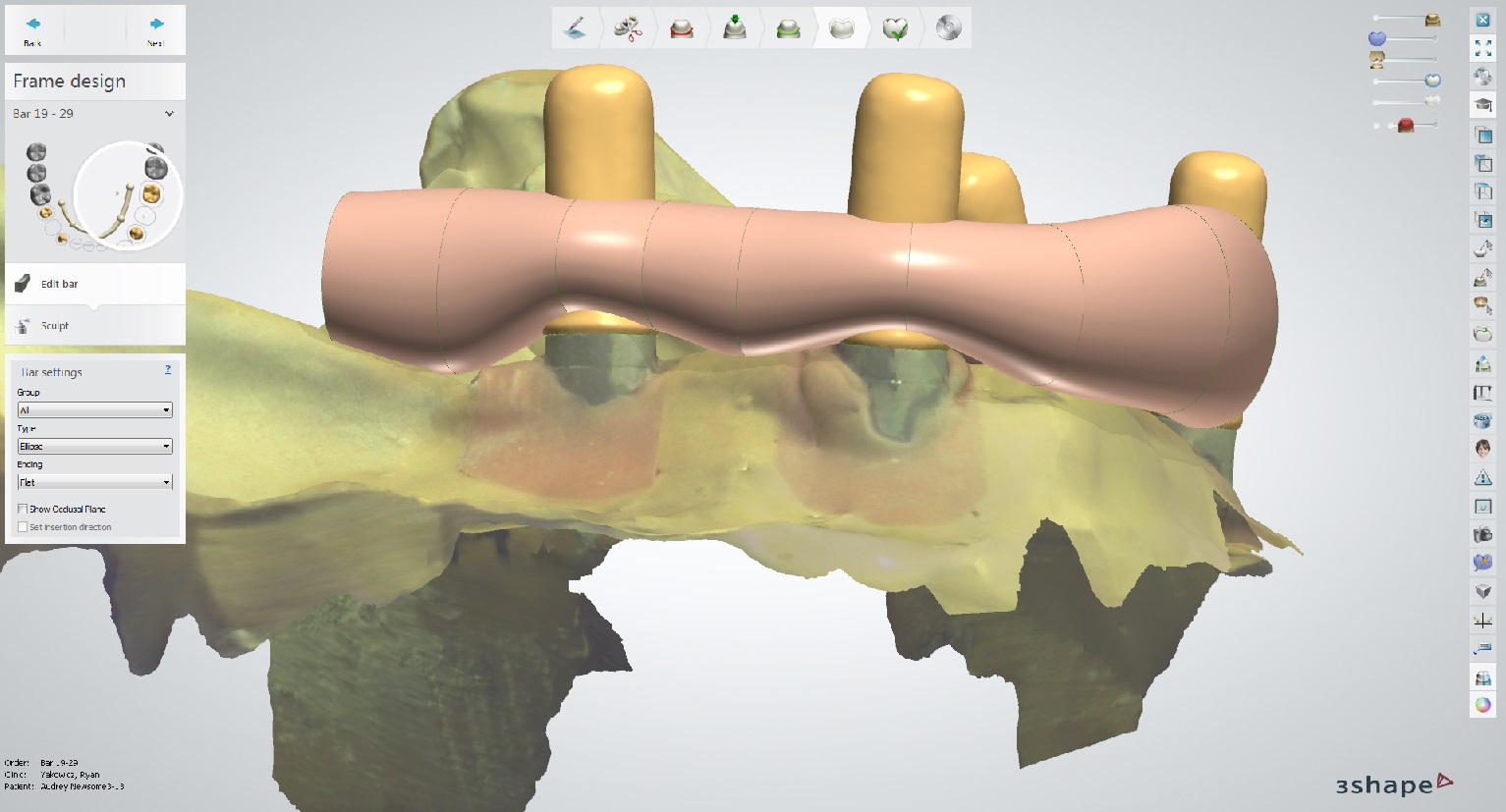
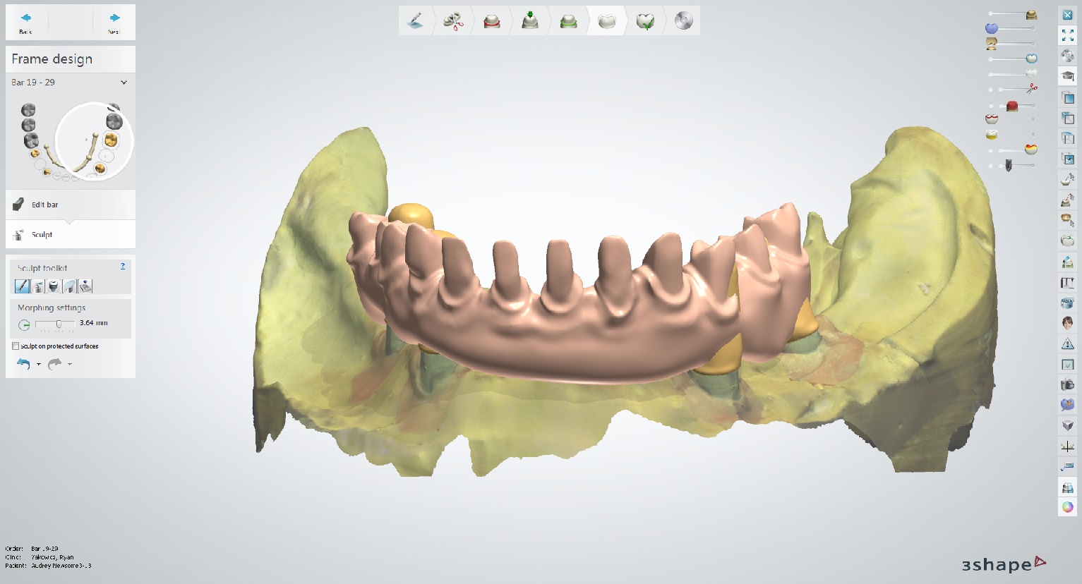
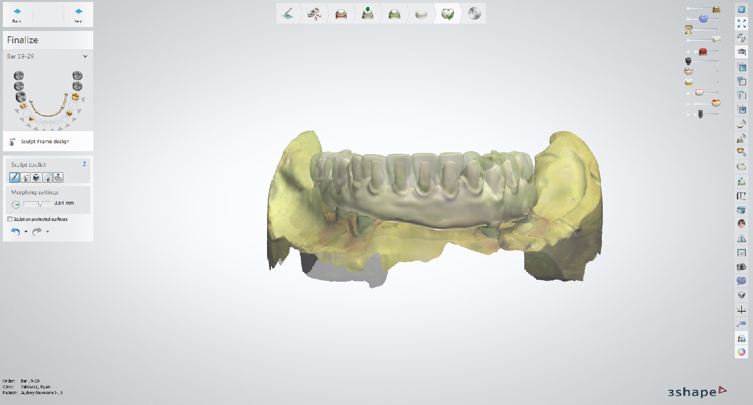
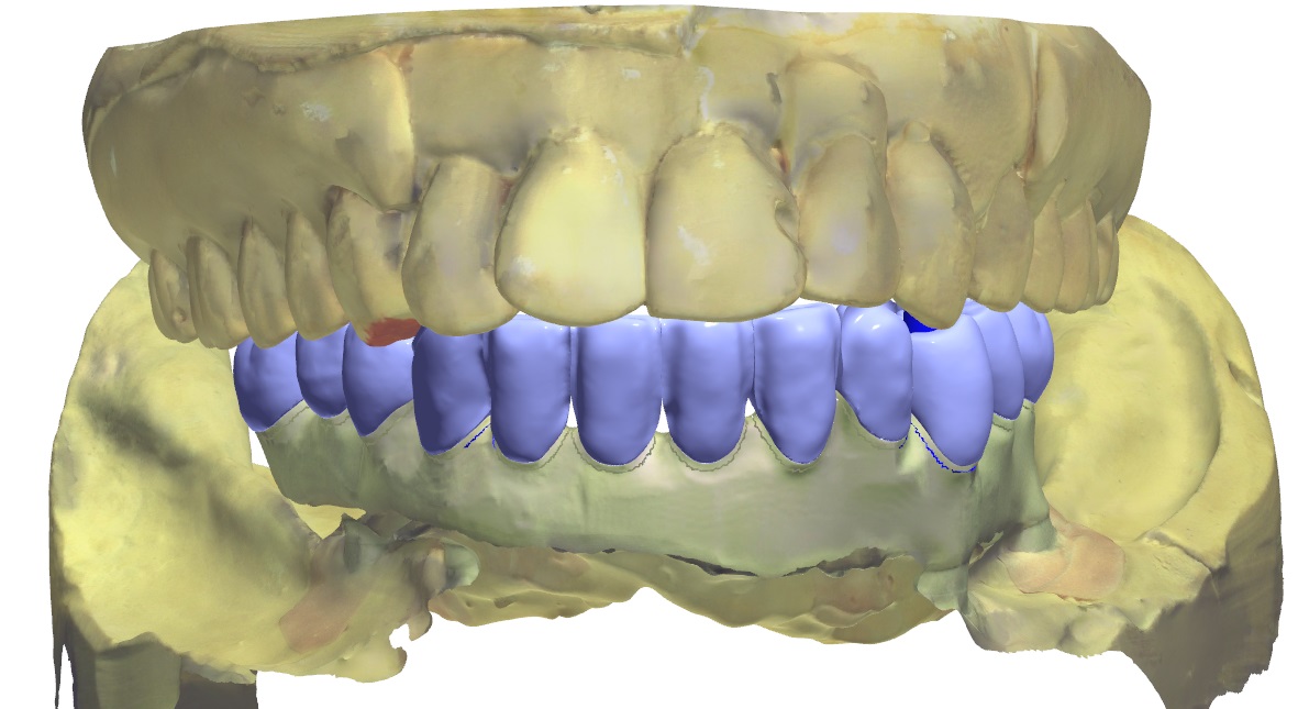
For this case, digital modalities were utilized to help create the final prosthesis. The existing model work was digitized, and a “crown down” digital design was created (figure 9a). Based on the overall occlusal scheme and tooth position, a framework was designed to accommodate individual eMax crowns on a PEEK (polyetheretherketone) framework hand layered with composite. A trial framework was milled out of PMMA to ensure fit to model, and, once verified, the framework was milled out of a PEEK puck, and cylinders to accommodate the intra-oral multi-base abutments were luted in place within the framework (figure 9b). Individual crown preps were milled into the framework design and the framework was re-scanned to design CAD/CAM crowns to the framework (figure 10). An adhesive bonding protocol exists for PEEK materials. As such, once the framework is roughened with a diamond bur, sandblasted with AlO2, and primed, an adhesive interface ensures solidarity of the components. After the eMax crowns are fired and glazed, they are conditioned before being bonded to the PEEK framework. Etching the intaglio surface of the crowns with 5% HF acid for 20 seconds followed by rinsing and drying and applying silane is done before the crowns are loaded with an adhesive resin cement and placed definitively onto the framework. The rest of the PEEK framework is hand layered in pink composite and cured, per manufacturer instructions. A glycerin barrier is applied before final curing to prevent the formation of an oxygen inhibited layer during the curing process, and the total prosthesis is highly polished (figure 11).
Figure 9a and 9b; Digital design of the prosthesis and the PMMA trial framework on the left and the definitive PEEK framework on the right.
Figure 10; Blue-phase individual eMax crowns fitted to the PEEK framework. The anterior is cutback for layering to amplify esthetics.
Figure 11; The fully processed definitive prosthesis (PEEK, eMax, Composite), ready for delivery.
Insertion protocol is relatively straightforward, given that the accuracy and passive fit of the prosthesis has been maintained during fabrication. The prosthesis fit is verified, and the occlusion is refined as necessary. The occlusal design has some set parameters, and some parameters that are dependent on the opposing arch.
Important things to always build into the design are:
Bilaterally identical occlusal contacts in the posterior and canines
Very slight to no contact on incisors
Freedom of movement through excursive movements (also referred to as “Freedom in Centric”)
No interferences on inclined planes (avoid any “tilting” forces)
Criteria for functional occlusion specific to opposing dentition include:
If opposing natural dentition/canines: Canine guidance.
If opposing implant supported frameworks: Group function with relatively flat cusps (less than the steepness of the condylar path, ascertained by the angle of the protrusive bite record) and limited vertical overlap.
If the implant supported prosthesis is opposed to removable partial denture, complete denture or implant supported over denture: Group function with a balancing contact to stabilize the removable prosthesis during function
The prosthesis is screwed into place with small bridge screws torqued to 15 Ncm each. An important part of the planning process for the prosthesis is location of the screw holes (figure 12). In this case, each screw hole was located on a lingual or occlusal surface of the prosthetic teeth. This is desirable in comparison to screw-holes that exit the body of the framework (gingiva) or in an esthetic area (facial or buccal surfaces of teeth). Once the screws are torqued into the multi-base abutments, polytetrafluoroethylene (PTFE) tape is placed over the screw access and covered with dentin shade or more opaque composite before a composite akin to the tooth shade is placed in an effort to combat a low value appearance of the screw access fill. The occlusion is adjusted as necessary and the composite restorations are polished.
Figure 12, Location of the screw access holes and access fill with composite, shown with initial occlusal markings.
Maintenance is an important and often overlooked part of this treatment. First, the prosthetic device should be designed with proper emergence profile and convex contours that enable spillways for debris. Second, patient hygiene practices are paramount. The patient is given a Waterpik and is asked to use it on a low setting (e.g. 3) to further facilitate debris removal from under the framework. The patient is asked to avoid the abutments with the Waterpik in an effort to protect the hemi-desmosomal connection to the multi-unit abutments. Instead, the patient is asked to use a Nimbus extra-soft bristled toothbrush to clean around the abutments. The recommended toothpaste is any low abrasive toothpaste in an effort to preserve the polish and luster of the restoration. The patient is also given Superlfoss for use under the bridge, and advised to use mouth rinse as he or she is willing or able. Lastly, the patient is scheduled for 1-year re-care visits (this timeline may be more or less frequent depending on patient risk factors or patient hygiene practices and how they relate to dutiful implant maintenance). The implants and associated tissues should be clinically evaluated and radiographs should be made at appropriate intervals. The Multi-Base Abutments should be cleansed of calculus or plaque using the correct instrumentation. Lastly, it is important to note that it is the position of the American College of Prosthodontists that removal of the prosthesis is not necessary unless there are “signs of peri-implantitis, a demonstrated inability to maintain adequate oral hygiene, or there are mechanical complications that require removal.”
As is evident by this journal entry, All-on-X treatment is complicated, and includes many treatment considerations. Esthetics, occlusion, biomechanics, surgical implant protocols, denture design, maintenance, and phonation all require attention and expertise if All-on-X treatment is to be performed. These types of prostheses can be very challenging, and require a lot of knowledge to execute properly. Ultimately, a well-made, full arch, implant supported prosthesis offers a high degree of satisfaction to provider and patient (figure 13a, 13b).
Figure 13a; Panoramic radiograph of the definitive prosthesis in place.
Figure 13b; A pre-operative (left) and post-operative view (right).
Dr. Ryan Yakowicz, DDS, FAGD
Dr. Yakowicz practices in the Greater Madison Area of South Central Wisconsin. Having completed over 775 hours of continuing education, his special interests include functionally cosmetic full mouth rehabilitation, TMD and oral-facial pain, and surgical implant placement and prosthetic restoration.
Dr. Yakowicz is currently the president of the Madison Dental Progress Forum Study Club and the Wisconsin Institute for Advanced Dental Education. He is a Fellow of the Academy of General Dentistry, and is a member of the American Academy of Cosmetic Dentistry, and the American Academy of Fixed Prosthodontics. Additionally, Dr. Yakowicz participates in research studies for the National Provider-Based Research Network and is an Ambassador to the National Health Service Corps
REFERENCES:
i) ACP Position Paper on the Maintenance of Full Arch Implant Restorations.
(https://www.prosthodontics.org/assets/1/7/Maintenance_of_Full-Arch_Implant_Restorations.pdf)
ii) Prosthodontic Perspective to All-On-4® Concept for Dental Implants
M Taruna,1 B Chittaranjan,2 N Sudheer,3 Suchita Tella,4 and Md. Abusaad5
J Clin Diagn Res. 2014 Oct; 8(10): ZE16–ZE19.
iii) Periodontol 2000. 2016 Jun;71(1):164-84. doi: 10.1111/prd.12122.
Post-treatment supportive care for the natural dentition and dental implants.
iv) Bonded Porcelain Restorations in the Anterior Dentition: A Biomimetic Approach (2003)
Quintessence Publishing Co, Chicago, IL
Magne, Pascal. Besler, Urs.
v) Dental Implant Prosthetics 2nd Edition. Elsevier Mosby, St. Louis, MO. Misch, C.


